DRONE PROJECT: ITERATION 1
OUTLINE
For this first iteration of the UAV project, the objectives will be quite simple. Using the body design of the referenced drone (inspired by recent trends in this style of design), the UAV must be able to maintain flight in the air, make basic maneuvers, and be controlled from a long range using an Xbox remote.
This design entails the following parts:
- Body and flaps (3D printed)
- Battery
- Microcontroller
- Brushless electric motor
- Receiver stack
- 4 servos
The general design and fabrication process can be outlined as follows:
1) Basic Design Outline
- List of components
- Body shape reference
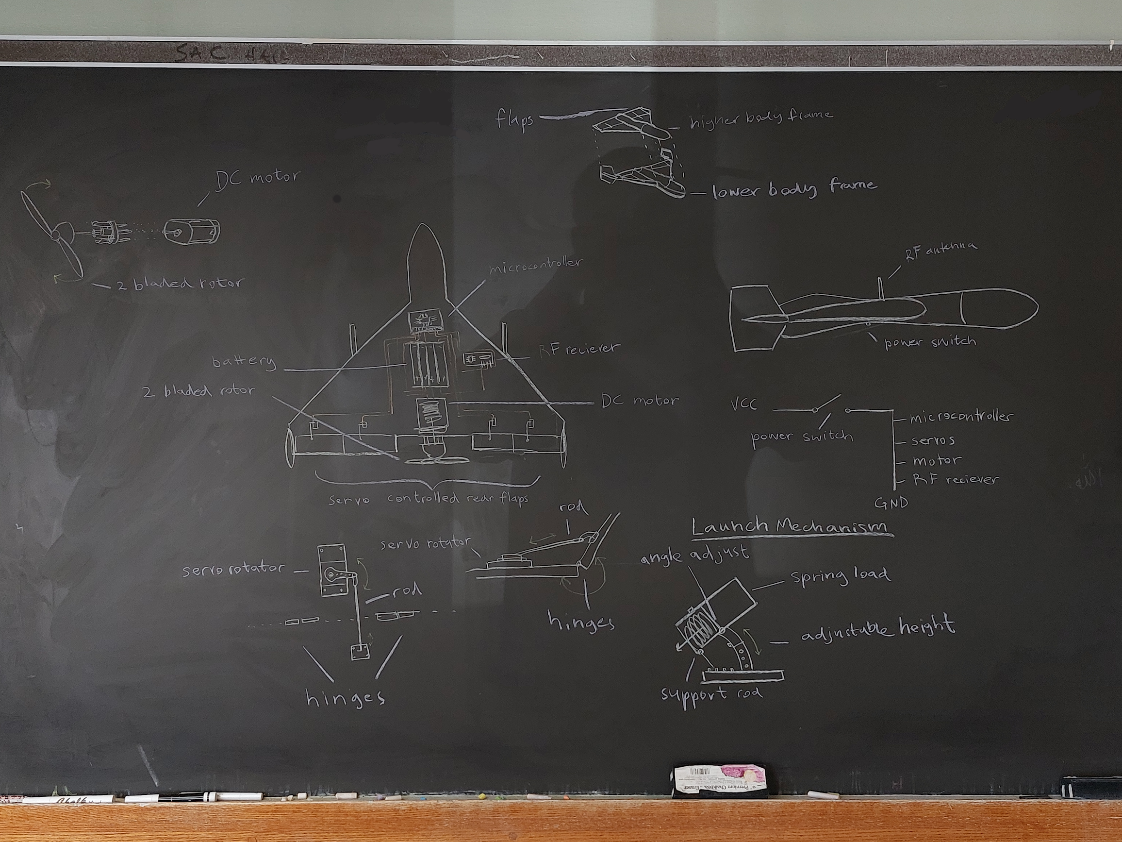
- Preliminary component mapping
2) 3D design
- Retopology of bask model
- Fitment of components
- Modular division
3) Physical Fabrication
- 3D printing
- Testing modular cohesion
- Component placement
4) Electrical engineering
- Wiring
- Controls + remote connection
- Program microcontroller
Planning
 Design
When designing the drone, I did extensive research into the relevant areas of aerodynamics and material properties, along with research on physical mechanisms and fabrication. Having selected and purchased the electronic components, I spent time measuring their dimensions and obtaining accurate 3D models of them. Sometimes, accurate models would be available online, but other times, I would have to create my own. In this part of the design phase, I chose airfoil shape, decided the shapes and divisions of parts, determined the materials, and drew new sketches which I could refer to while modeling.

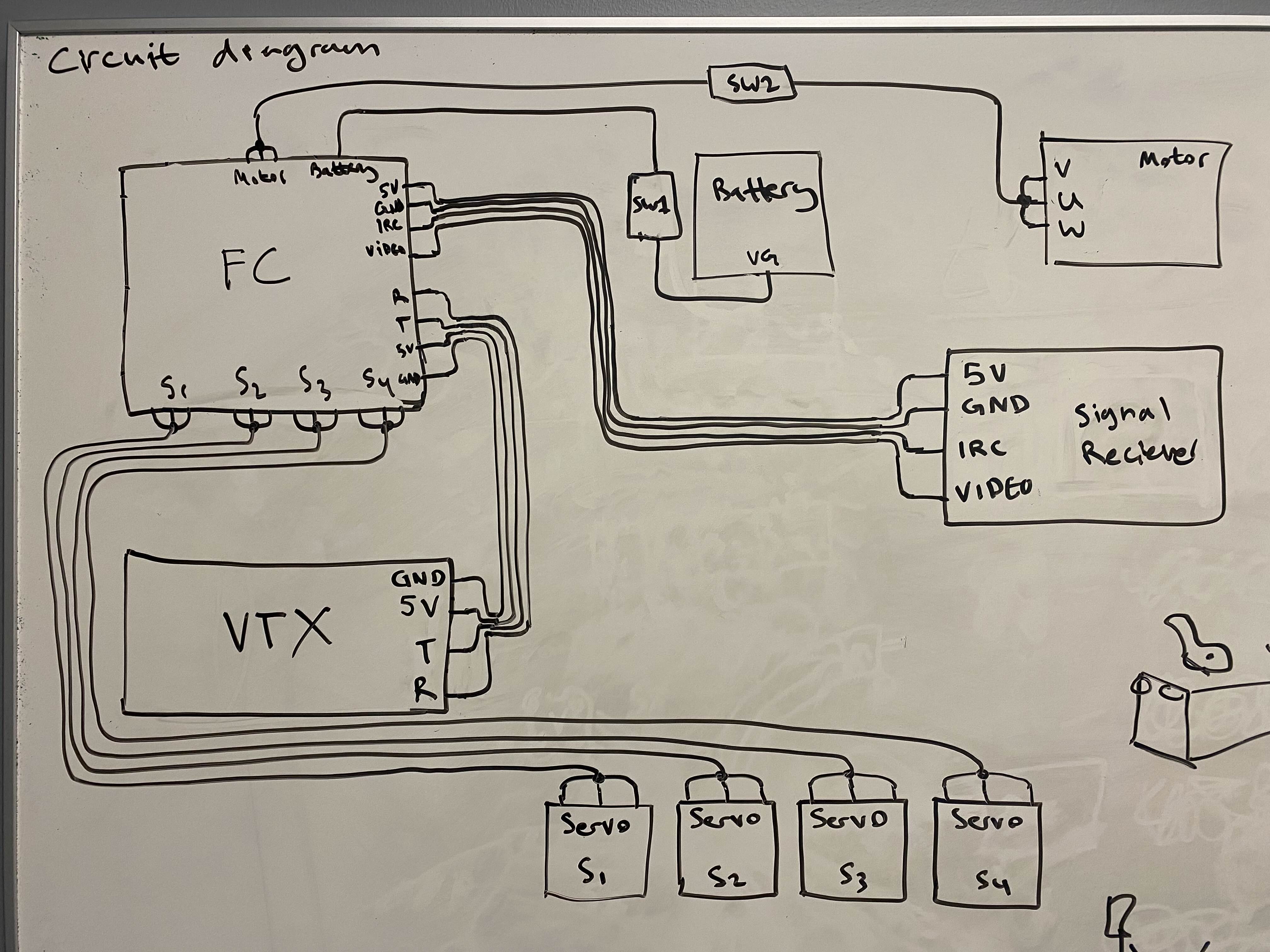
Preliminary connections diagram for electronic components:
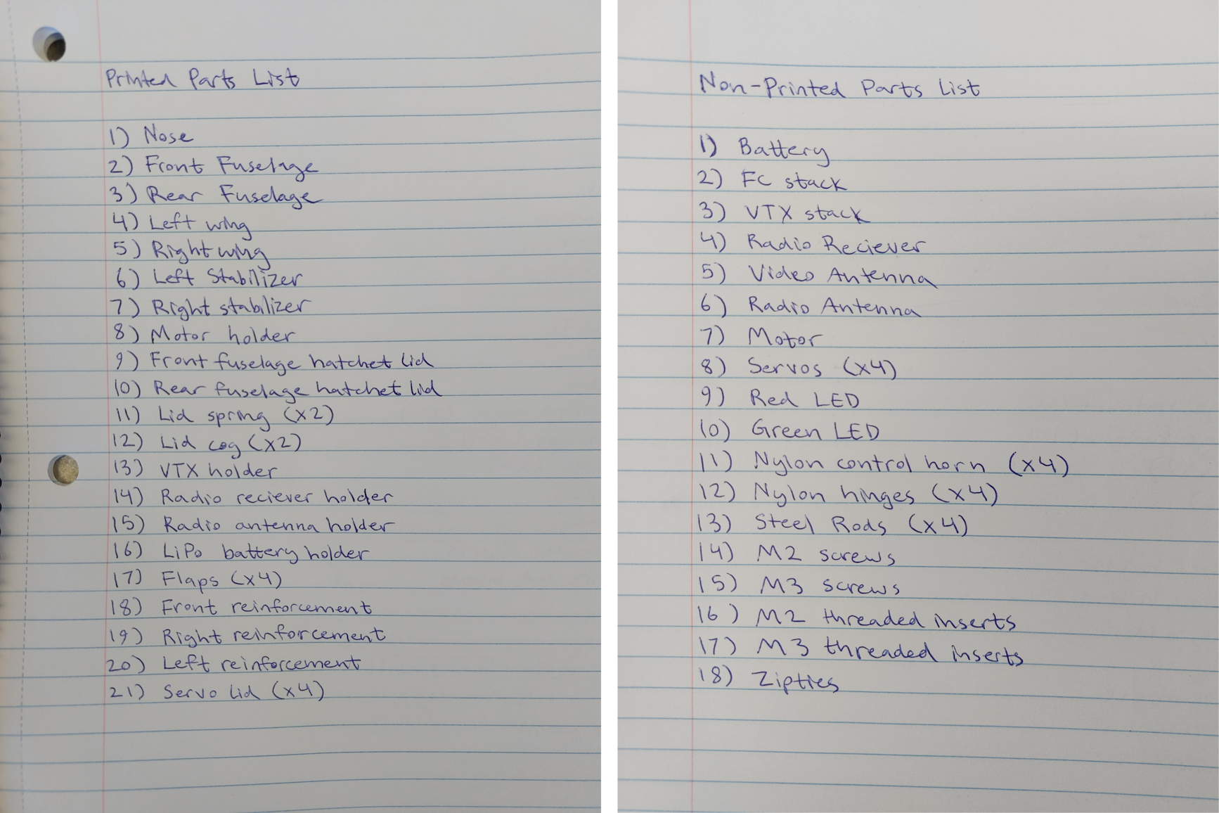
Exhaustive list of parts:
 3D Modeling
All 3D modeling was done in Blender. Initially, I had winged the modeling process but later restarted the entire model due to design flaws which were not reversible because of my method of modeling. The second time, I used a series of Boolean object modifiers to ensure that any modification to the model could be adjusted or undone at any point in the future. Additionally, I redesigned the division of the body into parts and the way they were to be assembled.

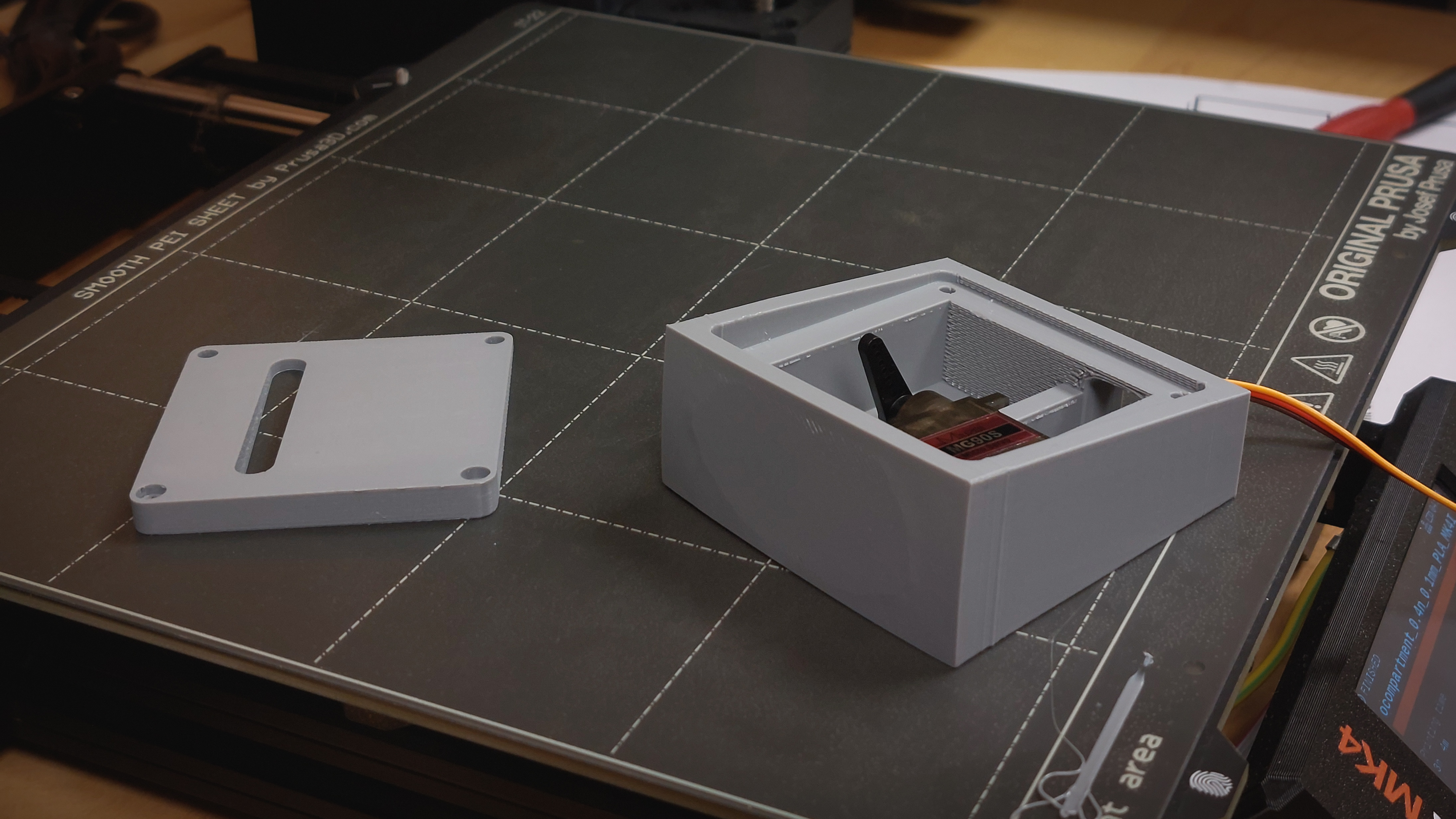
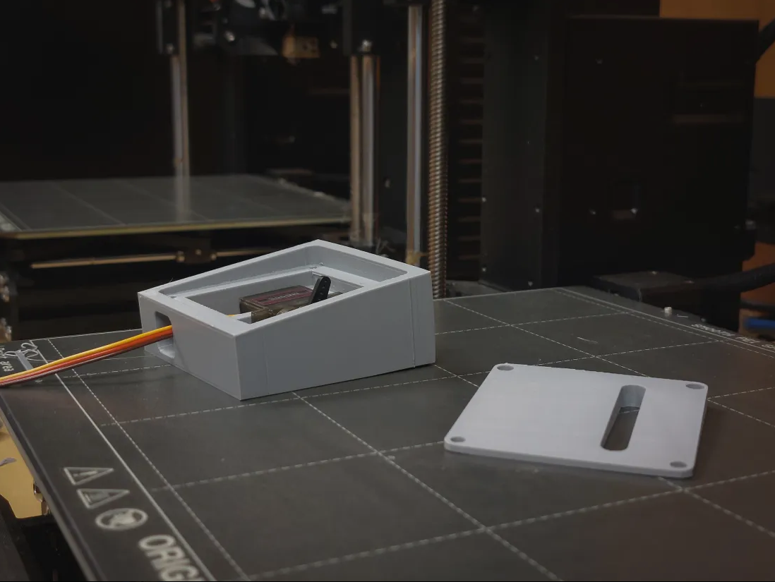
To fit the flap servos in the wing, I created a Boolean template for servo compartment in wing. For reference, the model of the servo is also included. Hot glue will suffice to hold the servo in place and yet allow for removal or replacement if needed.
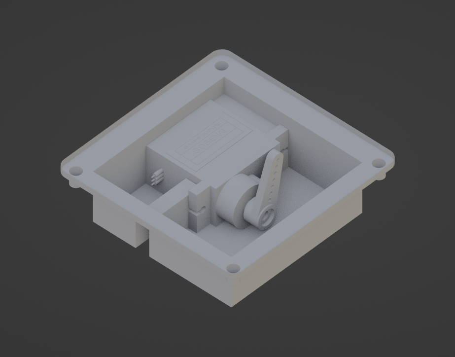
Applied Boolean modifiers:
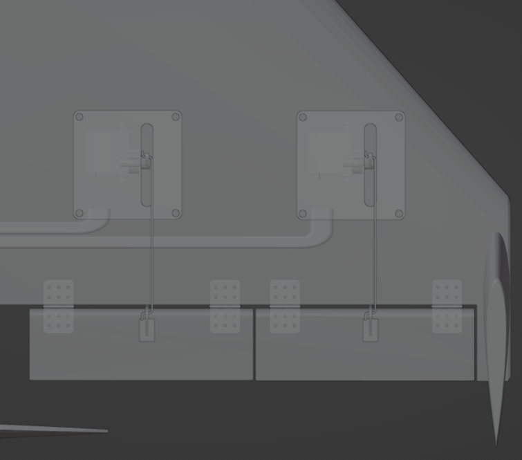
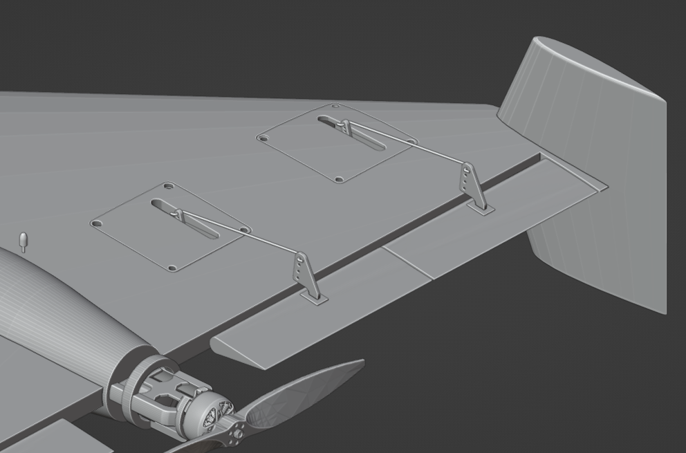
To control the flaps of the drone, the servos inside the compartments rotate to move the linkage mechanism. The servos are linked to the flaps through steel rods and control horns, which are to be attached to the flaps using strong adhesives. The flaps themselves are attached to the wing by nylon hinges that insert into the two parts.
 3D Printing & Rapid Prototyping
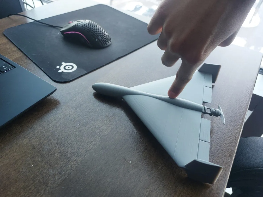
To get a feel for the shape of the drone, I printed a full solid 1/2 scale model of the drone. For the fun of it, I also specially modeled the propellor in this model to snap onto the motor holder cage and spin freely when flicked.
During rapid prototyping, I made sure not only to find the right tolerances for fitments, but also fix the weak points to ensure structural integrity of parts.
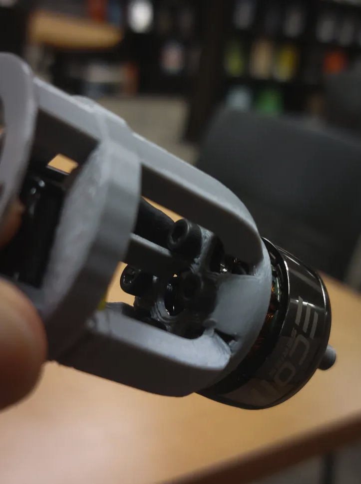
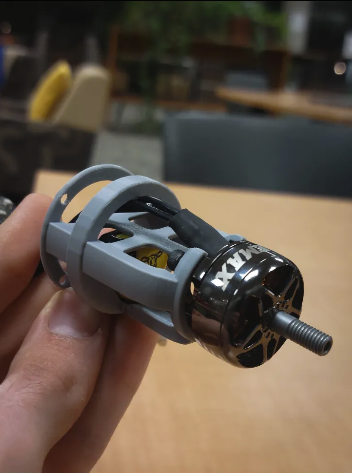
The motor holder cage, for example, was meant to hold in the motor by creating a perfect fit at its bottom and secure it using screws. At its base, the motor holder cage connected to the fuselage of the drone, from which the VTX antenna would poke out and snuggly rest in the cage. The print initially had some issues with the geometry of the model and the base was too thin, resulting in poor structural integrity and easy snapping. Once taken care of, the motor holder cage is finalized as its own part.
With the servo compartment, I found the tolerance that ensures that the lid fits properly. My biggest obstacle was warping of the print, which was eventually minimized.
CURRENT PROJECT STATUS
So far, I've learned a lot about the mechanical side of projects like these, giving me a better understanding of what my mechanical constraints are as well as my electrical ones. As rapid prototyping carries on, I have tested the microcontroller, the brushless motor (It spins really fast! 38k RPM!) and the servos. I also prepare to use both the wind tunnel in the Johnson Controls lab as well as CFD in Ansys. While I have the electronic components to configure and interface to each other, I am allowing myself to finish the tasks at hand first to avoid stretching out too thin. After all, he who chases two rabbits at once will catch neither, and that should serve as a wise lesson to engineers. There's still a long way to go, but I'm looking forward to it nonetheless.
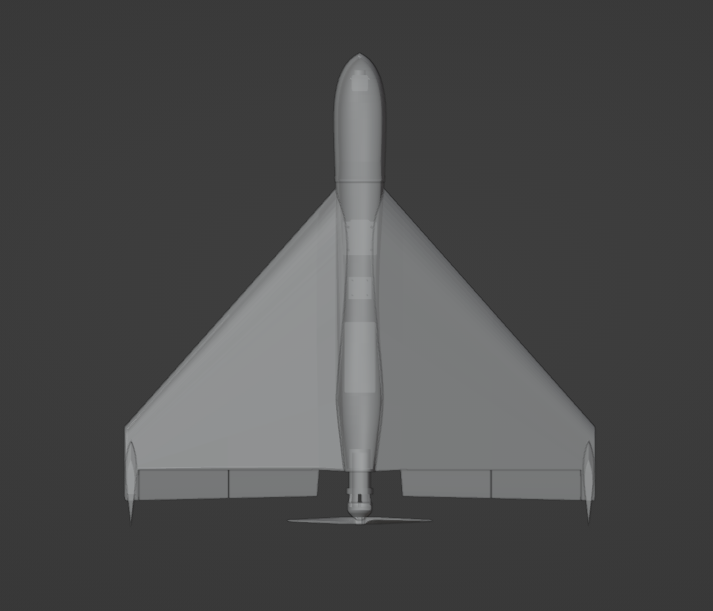
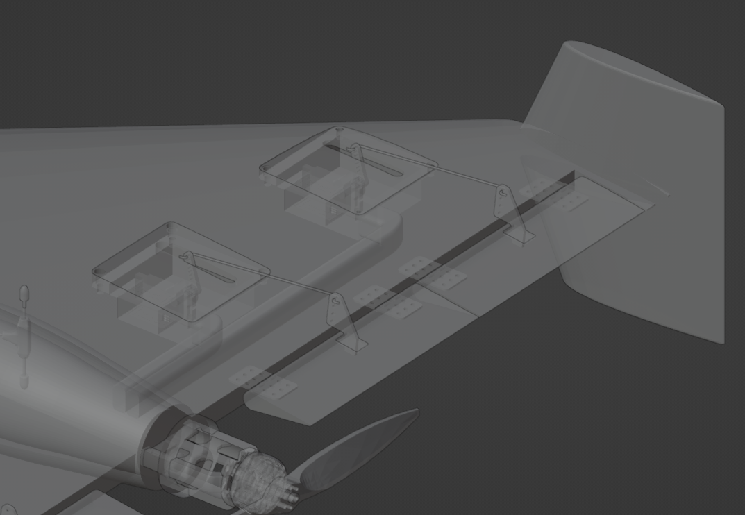
In the meantime, enjoy this epic rendered preview I made of the final product:

